Thursday, July 28, 2005
Technical feature of Formula One - Part One
FLUID DELIVERY SYSTEM
 It comes as no surprise that the physical effort of racing a Formula 1 car almost non-stop for over an hour is literally draining. Drivers can lose up to four litres of fluid from their bodies during a grand prix, so the need to keep hydrated is paramount. Thankfully for Kimi and Juan Pablo, Team McLaren Mercedes has a tried and tested method that ensures they are drinking enough both before and during a race.
Sucking liquid from a hand-held drinks bottle is part of the driver's pre-race preparation, often witnessed on the grid or in the garage. "We try and get as much fluid as possible into the driver leading up to the race to make sure they are well hydrated," says Mark Arnall, Kimi's personal trainer and therapist. "During the race, the cockpit gets very hot so there will be dehydration, which can effect the driver's performance. Our task is to make sure that dehydration is prevented."
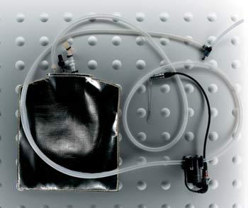
During the race, a slightly more complex system comes into place, with a medical IV drip bag acting as the drinks bottle, situated in the cockpit to the left hand side of the driver. A system of plastic piping and an electric pump transfer the liquid around the inside of the helmet into the driver’s mouth. When he wants a drink he pushes a button on the steering wheel to activate the system and inject the fluid, which is a simple solution – water!
Due to the forces acting on the car as it works its way around the circuit, it is conceivable that the drinks system could be activated and then fail to turn off. As sports drinks contain substances such as carbohydrates and can be sticky, it would be uncomfortable for them to be squirted onto the driver’s face and cloud the visor, so water is a more practical liquid to use.
There are some important external factors which will influence how much liquid a driver needs to consume during a race and therefore how much the fluid delivery system is used, such as humidity and temperature. "A driver always has to be 100% hydrated, but the conditions at each circuit can come into play," explains Arnall. "In Malaysia, for example, it is very hot and humid and therefore important to consume the drink, because the driver will lose a lot more fluid. In cooler conditions, such as we generally find in European grands prix, that need isn’t as great."
Furthermore, the fitness level of the driver and the handling of the car can influence the amount of effort he must put into driving, and thus the amount of fluid he will use. Unlike other components on a Formula 1 car, the method is unlikely to alter. "We've been using this system for a while," says Arnall. "So long as it’s doing the job there's no reason to change."
IN-CAR COMMUNICATIONS
 Communication is key to the success of any Formula 1 team, and this is never more important than during a race. The in-car communication system developed and deployed by Team McLaren Mercedes does exactly what the name suggests – it enables the driver to give and receive information while out on track.
The system has three main functions, the first being that it allows the team to issue instructions to the driver. This takes the form of controlling strategy, advising the driver of his position and informing him of unexpected events or conditions. Secondly, the in-car communication system is used by the driver to send feedback to the garage prior to a pit stop, allowing set-up changes to be prepared by the engineers and mechanics. Thirdly, in extreme circumstances, its use is vital to warn of an unscheduled stop caused by a racing incident, puncture or system failure.
The team aims to keep the group of people operating the system as small as possible, with just three key talkers involved for each car. This makes it possible to stick to the correct procedures during scheduled and unscheduled events throughout the race weekend.
Naturally, these key personnel include the driver and his race engineer, along with a member of the team’s management.
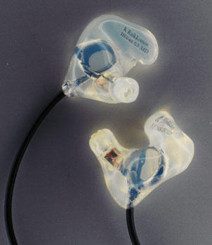
Team McLaren Mercedes has been working alongside Official Supplier Kenwood to develop its own in-car communication system for many years. The MP4-19B’s radio system is designated the CBX-780 and is located under the drivers’ knees on the floor of the car, while the microphone and ear pieces are fitted into the helmet. Inside the garage is a digital intercom system which converts the audio into data, a controller PC for monitoring and set-up of the system and repeater units which broadcast the radio signals across the circuit. Throughout the season changes are made to the basic system, which under technical regulations laid out by the sport’s governing body, the FIA, the team is free to develop as it wishes. “As with all other areas of Formula 1 car design, we are constantly looking for improvements, either in terms of packaging, performance, audio quality or security,” explains Phil Asbury, Head of Systems Engineering at McLaren Racing.
Similar to most components in a Formula 1 car, the in-car communication system must be as small and light as possible, so the packaging of the radio equipment is an important consideration. “If we develop a possibility to reduce the size or weight of the system, then we would certainly consider investing in this even if there are no other technical benefits,” says Asbury, who manages the system.
It is not only the team personnel who are privy to the mid-race conversations with the driver, as the FIA stipulates that it must have access to the audio channels between the drivers and the pits. This means that the team must route some of the audio channels from its radio and intercom communications system directly into the FIA intercom system off-air.
Technical Spec
Earpiece length: 492mm
Earpiece mould length: 27mm
Microphone unit length: 205mm
THE TRACK ROD
 The track rod is one of the more everyday components found on a Formula 1 car. But it is also one that illustrates just how incredibly high the stakes are in every single aspect of a car’s construction.
Put simply, a track rod is a carbon fibre rod that links the car’s steering rack with the front wheels. There is nothing ‘simple’, though, in the challenge of building a component that weighs just a few grams yet can withstand loadings of a ton as the car flies around the racetrack.
Lighter and stronger than the same item on a standard road car, a Formula 1 track rod also features greater adjustment. The angle of a car’s wheels – set to ‘toe-in’ or ‘toe-out’ by the race engineers – is vital to the temperature of the tyres and to a car’s handling. This is, after all, the link through which a driver gets a direct ‘feel’ for how his car is handling.
“There are many components on a car that don’t have a direct impact on the racing driver,” says design engineer Gareth Robinson, “but if a track rod were to fail, a driver would be left with no steering. When you build a component that is so massively safety critical, there is no margin for error – you just have to get it right.”
The component is manufactured from carbon fibre for extra stiffness and strength. To appreciate why, you need look no further than the slow-motion replays of the cars’ wheels banging over the kerbs in a grand prix.
“If you look at a telemetry trace of the loadings on a track rod, you can clearly see the peak loads as it hits the kerb,” reveals Robinson. “It has a very severe fatigue cycle because the loadings switch from compression to tension very quickly.”
Heat is also a factor. Where a standard track rod will operate at ambient temperature, in a Formula 1 car the component is positioned close to the brake discs and can reach temperatures of around 100 degrees C. To legislate for that, the carbon is cured at 150 degrees earlier in the manufacturing process.
In a structural engineer’s ideal world, a carbon component is as straight as possible because that is how the material transmits the loadings on it most efficiently. A complete Formula 1 track rod, though, is shaped something like a hockey stick.
“The car has to be a team effort, and there are a lot of aerodynamic constraints that have to be satisfied,” explains Robinson. “The packaging of a Formula 1 car is so tight in this area. The shape of the track rod has to be compromised to accommodate the steering lock and also to make as much room as possible for the brake ducts.”
Aerodynamics are critical in Formula 1. So vital to performance is the airflow over and around the car that the rod features a blunt trailing edge that enables it to be incorporated within the front suspension’s aerodynamic shroud.
To these constraints you can add the quest to eliminate friction from all joints in the suspension, which will further improve a driver’s feel for his car.
The track rod may be “simple”, but the manufacture of each individual component still involves 25 different design drawings and at least 40 man-hours. It’s enough to make you wonder what a complex component is like.
FLUID THINKING
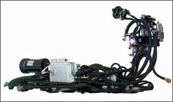
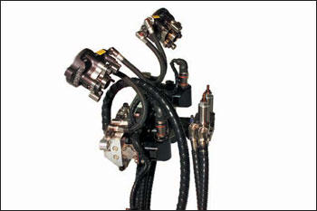
 As modern technologies go, hydraulics might not seem that sexy. For a start, the basic science has been around since the time of the Ancient Greeks. Apart from that, most of us have come to associate hydraulics with lifts, hoists and presses – in other words big, ponderous machinery.
So it comes as a bit of a surprise to find that hydraulic systems played an extensive and absolutely vital role in the Team McLaren Mercedes MP4-19B. Without them, the car would have been going nowhere fast. Or even slow, come to that. Quite simply, hydraulics are what run the car’s vital systems.
The throttle and air intake, clutch, gearshift and differential are all hydraulically-operated, as are the brakes, power steering and even the fuel filler cap.
“Computer control systems and algorithms are very powerful, but mechanically they can’t actually drive things,” explains Phil Mackereth, the Hydraulic Systems Design Engineer at Team McLaren Mercedes.
Fluid Power Technology is the term used these days to define the sort of state-of-the-art hydraulic engineering that goes into a modern Formula 1 car. It’s only in the past 15 years that the introduction of fully automated gearshifts and traction control has led to the development of sophisticated hydraulic systems to run the engine and gearbox.
 Up until the advent of automated, computer-controlled gearshifts in the late 1980s and early ’90s, all racing drivers changed gear by using a clutch pedal, a throttle pedal and manual gear lever. Now they simply have to press the paddle on the steering wheel, whereupon the car’s on-board computer makes all the necessary timing calculations and instructs the hydraulic system to carry out the mechanical operations involved. This is then achieved by pumping hydraulic fluid around a pipe circuit at a pressure of 200 bar and a temperature of 120ºC, via a series of computer-controlled servo valves - an electro-mechanical device that opens and closes in response to commands from the car’s engine management computer. These control the flow of fluid to the actuators, which perform a mechanical action in response to an input signal, on the engine and gearbox.
One key advantage of electro-hydraulic systems is the enormous power gain they develop relative to the electronic command signal. “When you run a system at very high pressure, as we do,” says Mackereth, “it provides you with a great deal of power and speed at your fingertips for very little power input and this, in turn, means that you can make things happen extremely quickly and in a highly controlled way.
“In this instance, the computer generates tiny amounts of electricity, but these are amplified through the servo valves by 25,000 times, making it possible to complete a gear shift in under 50 milliseconds.”
There will be between 3,000 and 3,500 gear shifts during the course of a race and, apart from enabling the driver to carry out a much quicker and more reliable shift, an automated hydraulic system reduces the risk of damage to the engine or gearbox.
 “In the days before we had hydraulic gear shifts, engines and gearboxes would break and it could often be the driver’s fault for mis-timing the shift or over-revving the engine,” recalls Mackereth. “These days, it’s never the driver’s fault if that happens. The system ensures that every gear shift is perfectly synchronised.”
Hydraulic throttle control is also a useful part of traction control. The accelerator pedal position is only one of the inputs into the car’s computer, which ultimately governs the amount of power produced by the engine. If the engine is asked for too much power and the computer thinks the car might skid, it will over-ride the demand and reduce power.
Although there are many conflicting views about the use of traction control the team would not return to pedal-and-cable style throttle control, according to Mackereth. “There are too many other advantages to be gained from using hydraulics,” he points out. “You need to do some very precise and high-speed things with the throttle during a gear change if you’re to get the engine to allow you to disengage a gear and re-engage another without the risk of breaking things.”
The use of hydraulics in controlling the flow of air into the engine is especially ingenious. Each cylinder is topped by a trumpet, the metal tubing down which air is drawn into each cylinder. At one time these trumpets were of fixed length, but ideally you need them to be of different lengths depending on the engine speed and power settings – short for high engine speeds, longer for lower speeds. The MP4-19B featured a system whereby you can alter the lengths of the trumpets hydraulically, little actuators shunting them up and down as required.
 The majority of the MP4-19B’s hydraulics ran off one main system. The brakes work off a separate, self-contained hydraulic system, which also uses a different fluid. As for the power steering, although it takes its fluid from the same system, the rules stipulate that this has to be a mechanical rather than an electronic device and so it is operated using a valve similar to the type found in a road car.
Mackereth’s brief for MP4-19B was to make sure that the entire hydraulics system were as light, compact and unobtrusive as possible, without compromising strength and reliability. This entailed not only making the components as small as possible but also packing them as closely as possible so that fewer lengths of piping are needed to join them together.
“The push for the past few years has been to bring all the main components together in one pack,” he explains. “This is bolted to the side of the engine, just below the exhausts. It’s important to have it fitted as low as possible so it doesn’t raise the car’s centre of gravity too much. At the same time, this brings the advantage of freeing up space elsewhere on the engine and gearbox so that other things can be done more effectively.
“The hydraulics system is quite complex, involving a lot of expensive, highly machined components and a good design will last a whole season with minimal changes. That’s the objective. I always know what I’ve got to provide well in advance.
“Design continuously improves the car, including the engine and gearbox. Such changes are frequent, and are designed into each car from the start.”
According to Phil, reliability is his main concern, because if his hydraulic systems stop working then the car pretty much stops straightaway. Proof enough of just how crucial hydraulic systems are in modern Formula 1.
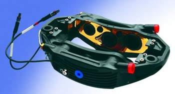
THE BRAKE CALIPER
 Racing on a circuit such as Monza, in Italy, drivers regularly brake from more than 350km/h to less than 100km/h. That demands world-class engineering such as that embodied in the Team McLaren Mercedes brake caliper.
The caliper is located on the car’s upright assembly, which is buried inside each wheel, and its primary function is to apply pressure to the brake pads, forcing them into contact with the brake disc.
“When the brake pedal is pressed by the driver,” explains Head of Race Engineering Steve Hallam, “it applies hydraulic pressure, via a master cylinder, into the caliper. This forces the caliper’s six pistons [which sit in the round holes within the inner surface] out of the caliper, squeezing the two brake pads against the disc and thus slowing the car. When the driver relaxes his foot from the pedal, the pressure on the hydraulic system is released and the caliper and pads relax, freeing the car to accelerate when the driver applies the throttle.”
There are, of course, four brake calipers on the car – one at each corner. The rear calipers are slightly smaller than the front ones because the car’s braking distribution is biased towards the front, as Hallam explains. “When a car brakes, it transfers weight onto the front axle and therefore the front wheels have more capacity to brake – and, because it’s transferring weight onto the front axle, it’s transferring weight off the rear axle, so the rear wheels have less capacity to brake compared with the front ones.”
A different brake specification can be used for circuits where heavier braking is required such as Montreal, in Canada, and Monza. This will have been planned for over the winter. Apart from that, the design doesn’t change much from year to year. It’s more a case of reducing weight by a few grammes than of making huge technological leaps.
In terms of design requirements, the caliper has to be light and stiff – as does any racing car component. If the caliper were flexible, the driver would experience a ‘spongey’ brake pedal – which is the last thing he wants at more than 300km/h. The caliper also has to be very durable. Friction between the pad and disc can generate temperatures of 1,000 degrees Celsius.
Operating in this harsh environment of high temperatures, and being subject to massive mechanical forces, the caliper requires cooling while in operation. Consequently, it needs to be fed with air from the brake duct (which directs air onto the brakes to cool them) and there are cooling fins on the caliper’s side, helping to keep the temperatures under control while the car is out on the track.
Of course, it’s not only racing cars that need to stop when the heat is on. Perhaps surprisingly, road car brake calipers are recognisably similar to the Formula 1 variety. Hallam explains that the caliper on a small road car might contain only one piston, or one pair of pistons, whereas a top-end car such as the Mercedes-Benz SLR McLaren will have a larger caliper.
“You’d be able to put the three calipers side by side and recognise them as one and the same thing,” Hallam says. The main difference, then, is that the road car doesn’t have to decelerate by 250km/h in just a few metres, for the racing car alone enjoys the exhilaration of braking at Monza.
TECHNICAL SPECIFICATION
DIMENSIONS: Width 255mm, depth 170mm, height 60mm, weight 1,570g
MATERIAL: Aluminium alloy
NUMBER USED PER SEASON: 50-60
 It comes as no surprise that the physical effort of racing a Formula 1 car almost non-stop for over an hour is literally draining. Drivers can lose up to four litres of fluid from their bodies during a grand prix, so the need to keep hydrated is paramount. Thankfully for Kimi and Juan Pablo, Team McLaren Mercedes has a tried and tested method that ensures they are drinking enough both before and during a race.
Sucking liquid from a hand-held drinks bottle is part of the driver's pre-race preparation, often witnessed on the grid or in the garage. "We try and get as much fluid as possible into the driver leading up to the race to make sure they are well hydrated," says Mark Arnall, Kimi's personal trainer and therapist. "During the race, the cockpit gets very hot so there will be dehydration, which can effect the driver's performance. Our task is to make sure that dehydration is prevented."
During the race, a slightly more complex system comes into place, with a medical IV drip bag acting as the drinks bottle, situated in the cockpit to the left hand side of the driver. A system of plastic piping and an electric pump transfer the liquid around the inside of the helmet into the driver’s mouth. When he wants a drink he pushes a button on the steering wheel to activate the system and inject the fluid, which is a simple solution – water!
Due to the forces acting on the car as it works its way around the circuit, it is conceivable that the drinks system could be activated and then fail to turn off. As sports drinks contain substances such as carbohydrates and can be sticky, it would be uncomfortable for them to be squirted onto the driver’s face and cloud the visor, so water is a more practical liquid to use.
There are some important external factors which will influence how much liquid a driver needs to consume during a race and therefore how much the fluid delivery system is used, such as humidity and temperature. "A driver always has to be 100% hydrated, but the conditions at each circuit can come into play," explains Arnall. "In Malaysia, for example, it is very hot and humid and therefore important to consume the drink, because the driver will lose a lot more fluid. In cooler conditions, such as we generally find in European grands prix, that need isn’t as great."
Furthermore, the fitness level of the driver and the handling of the car can influence the amount of effort he must put into driving, and thus the amount of fluid he will use. Unlike other components on a Formula 1 car, the method is unlikely to alter. "We've been using this system for a while," says Arnall. "So long as it’s doing the job there's no reason to change."
IN-CAR COMMUNICATIONS
 Communication is key to the success of any Formula 1 team, and this is never more important than during a race. The in-car communication system developed and deployed by Team McLaren Mercedes does exactly what the name suggests – it enables the driver to give and receive information while out on track.
The system has three main functions, the first being that it allows the team to issue instructions to the driver. This takes the form of controlling strategy, advising the driver of his position and informing him of unexpected events or conditions. Secondly, the in-car communication system is used by the driver to send feedback to the garage prior to a pit stop, allowing set-up changes to be prepared by the engineers and mechanics. Thirdly, in extreme circumstances, its use is vital to warn of an unscheduled stop caused by a racing incident, puncture or system failure.
The team aims to keep the group of people operating the system as small as possible, with just three key talkers involved for each car. This makes it possible to stick to the correct procedures during scheduled and unscheduled events throughout the race weekend.
Naturally, these key personnel include the driver and his race engineer, along with a member of the team’s management.
Team McLaren Mercedes has been working alongside Official Supplier Kenwood to develop its own in-car communication system for many years. The MP4-19B’s radio system is designated the CBX-780 and is located under the drivers’ knees on the floor of the car, while the microphone and ear pieces are fitted into the helmet. Inside the garage is a digital intercom system which converts the audio into data, a controller PC for monitoring and set-up of the system and repeater units which broadcast the radio signals across the circuit. Throughout the season changes are made to the basic system, which under technical regulations laid out by the sport’s governing body, the FIA, the team is free to develop as it wishes. “As with all other areas of Formula 1 car design, we are constantly looking for improvements, either in terms of packaging, performance, audio quality or security,” explains Phil Asbury, Head of Systems Engineering at McLaren Racing.
Similar to most components in a Formula 1 car, the in-car communication system must be as small and light as possible, so the packaging of the radio equipment is an important consideration. “If we develop a possibility to reduce the size or weight of the system, then we would certainly consider investing in this even if there are no other technical benefits,” says Asbury, who manages the system.
It is not only the team personnel who are privy to the mid-race conversations with the driver, as the FIA stipulates that it must have access to the audio channels between the drivers and the pits. This means that the team must route some of the audio channels from its radio and intercom communications system directly into the FIA intercom system off-air.
Technical Spec
Earpiece length: 492mm
Earpiece mould length: 27mm
Microphone unit length: 205mm
THE TRACK ROD
 The track rod is one of the more everyday components found on a Formula 1 car. But it is also one that illustrates just how incredibly high the stakes are in every single aspect of a car’s construction.
Put simply, a track rod is a carbon fibre rod that links the car’s steering rack with the front wheels. There is nothing ‘simple’, though, in the challenge of building a component that weighs just a few grams yet can withstand loadings of a ton as the car flies around the racetrack.
Lighter and stronger than the same item on a standard road car, a Formula 1 track rod also features greater adjustment. The angle of a car’s wheels – set to ‘toe-in’ or ‘toe-out’ by the race engineers – is vital to the temperature of the tyres and to a car’s handling. This is, after all, the link through which a driver gets a direct ‘feel’ for how his car is handling.
“There are many components on a car that don’t have a direct impact on the racing driver,” says design engineer Gareth Robinson, “but if a track rod were to fail, a driver would be left with no steering. When you build a component that is so massively safety critical, there is no margin for error – you just have to get it right.”
The component is manufactured from carbon fibre for extra stiffness and strength. To appreciate why, you need look no further than the slow-motion replays of the cars’ wheels banging over the kerbs in a grand prix.
“If you look at a telemetry trace of the loadings on a track rod, you can clearly see the peak loads as it hits the kerb,” reveals Robinson. “It has a very severe fatigue cycle because the loadings switch from compression to tension very quickly.”
Heat is also a factor. Where a standard track rod will operate at ambient temperature, in a Formula 1 car the component is positioned close to the brake discs and can reach temperatures of around 100 degrees C. To legislate for that, the carbon is cured at 150 degrees earlier in the manufacturing process.
In a structural engineer’s ideal world, a carbon component is as straight as possible because that is how the material transmits the loadings on it most efficiently. A complete Formula 1 track rod, though, is shaped something like a hockey stick.
“The car has to be a team effort, and there are a lot of aerodynamic constraints that have to be satisfied,” explains Robinson. “The packaging of a Formula 1 car is so tight in this area. The shape of the track rod has to be compromised to accommodate the steering lock and also to make as much room as possible for the brake ducts.”
Aerodynamics are critical in Formula 1. So vital to performance is the airflow over and around the car that the rod features a blunt trailing edge that enables it to be incorporated within the front suspension’s aerodynamic shroud.
To these constraints you can add the quest to eliminate friction from all joints in the suspension, which will further improve a driver’s feel for his car.
The track rod may be “simple”, but the manufacture of each individual component still involves 25 different design drawings and at least 40 man-hours. It’s enough to make you wonder what a complex component is like.
FLUID THINKING
 As modern technologies go, hydraulics might not seem that sexy. For a start, the basic science has been around since the time of the Ancient Greeks. Apart from that, most of us have come to associate hydraulics with lifts, hoists and presses – in other words big, ponderous machinery.
So it comes as a bit of a surprise to find that hydraulic systems played an extensive and absolutely vital role in the Team McLaren Mercedes MP4-19B. Without them, the car would have been going nowhere fast. Or even slow, come to that. Quite simply, hydraulics are what run the car’s vital systems.
The throttle and air intake, clutch, gearshift and differential are all hydraulically-operated, as are the brakes, power steering and even the fuel filler cap.
“Computer control systems and algorithms are very powerful, but mechanically they can’t actually drive things,” explains Phil Mackereth, the Hydraulic Systems Design Engineer at Team McLaren Mercedes.
Fluid Power Technology is the term used these days to define the sort of state-of-the-art hydraulic engineering that goes into a modern Formula 1 car. It’s only in the past 15 years that the introduction of fully automated gearshifts and traction control has led to the development of sophisticated hydraulic systems to run the engine and gearbox.
 Up until the advent of automated, computer-controlled gearshifts in the late 1980s and early ’90s, all racing drivers changed gear by using a clutch pedal, a throttle pedal and manual gear lever. Now they simply have to press the paddle on the steering wheel, whereupon the car’s on-board computer makes all the necessary timing calculations and instructs the hydraulic system to carry out the mechanical operations involved. This is then achieved by pumping hydraulic fluid around a pipe circuit at a pressure of 200 bar and a temperature of 120ºC, via a series of computer-controlled servo valves - an electro-mechanical device that opens and closes in response to commands from the car’s engine management computer. These control the flow of fluid to the actuators, which perform a mechanical action in response to an input signal, on the engine and gearbox.
One key advantage of electro-hydraulic systems is the enormous power gain they develop relative to the electronic command signal. “When you run a system at very high pressure, as we do,” says Mackereth, “it provides you with a great deal of power and speed at your fingertips for very little power input and this, in turn, means that you can make things happen extremely quickly and in a highly controlled way.
“In this instance, the computer generates tiny amounts of electricity, but these are amplified through the servo valves by 25,000 times, making it possible to complete a gear shift in under 50 milliseconds.”
There will be between 3,000 and 3,500 gear shifts during the course of a race and, apart from enabling the driver to carry out a much quicker and more reliable shift, an automated hydraulic system reduces the risk of damage to the engine or gearbox.
 “In the days before we had hydraulic gear shifts, engines and gearboxes would break and it could often be the driver’s fault for mis-timing the shift or over-revving the engine,” recalls Mackereth. “These days, it’s never the driver’s fault if that happens. The system ensures that every gear shift is perfectly synchronised.”
Hydraulic throttle control is also a useful part of traction control. The accelerator pedal position is only one of the inputs into the car’s computer, which ultimately governs the amount of power produced by the engine. If the engine is asked for too much power and the computer thinks the car might skid, it will over-ride the demand and reduce power.
Although there are many conflicting views about the use of traction control the team would not return to pedal-and-cable style throttle control, according to Mackereth. “There are too many other advantages to be gained from using hydraulics,” he points out. “You need to do some very precise and high-speed things with the throttle during a gear change if you’re to get the engine to allow you to disengage a gear and re-engage another without the risk of breaking things.”
The use of hydraulics in controlling the flow of air into the engine is especially ingenious. Each cylinder is topped by a trumpet, the metal tubing down which air is drawn into each cylinder. At one time these trumpets were of fixed length, but ideally you need them to be of different lengths depending on the engine speed and power settings – short for high engine speeds, longer for lower speeds. The MP4-19B featured a system whereby you can alter the lengths of the trumpets hydraulically, little actuators shunting them up and down as required.
 The majority of the MP4-19B’s hydraulics ran off one main system. The brakes work off a separate, self-contained hydraulic system, which also uses a different fluid. As for the power steering, although it takes its fluid from the same system, the rules stipulate that this has to be a mechanical rather than an electronic device and so it is operated using a valve similar to the type found in a road car.
Mackereth’s brief for MP4-19B was to make sure that the entire hydraulics system were as light, compact and unobtrusive as possible, without compromising strength and reliability. This entailed not only making the components as small as possible but also packing them as closely as possible so that fewer lengths of piping are needed to join them together.
“The push for the past few years has been to bring all the main components together in one pack,” he explains. “This is bolted to the side of the engine, just below the exhausts. It’s important to have it fitted as low as possible so it doesn’t raise the car’s centre of gravity too much. At the same time, this brings the advantage of freeing up space elsewhere on the engine and gearbox so that other things can be done more effectively.
“The hydraulics system is quite complex, involving a lot of expensive, highly machined components and a good design will last a whole season with minimal changes. That’s the objective. I always know what I’ve got to provide well in advance.
“Design continuously improves the car, including the engine and gearbox. Such changes are frequent, and are designed into each car from the start.”
According to Phil, reliability is his main concern, because if his hydraulic systems stop working then the car pretty much stops straightaway. Proof enough of just how crucial hydraulic systems are in modern Formula 1.
THE BRAKE CALIPER
 Racing on a circuit such as Monza, in Italy, drivers regularly brake from more than 350km/h to less than 100km/h. That demands world-class engineering such as that embodied in the Team McLaren Mercedes brake caliper.
The caliper is located on the car’s upright assembly, which is buried inside each wheel, and its primary function is to apply pressure to the brake pads, forcing them into contact with the brake disc.
“When the brake pedal is pressed by the driver,” explains Head of Race Engineering Steve Hallam, “it applies hydraulic pressure, via a master cylinder, into the caliper. This forces the caliper’s six pistons [which sit in the round holes within the inner surface] out of the caliper, squeezing the two brake pads against the disc and thus slowing the car. When the driver relaxes his foot from the pedal, the pressure on the hydraulic system is released and the caliper and pads relax, freeing the car to accelerate when the driver applies the throttle.”
There are, of course, four brake calipers on the car – one at each corner. The rear calipers are slightly smaller than the front ones because the car’s braking distribution is biased towards the front, as Hallam explains. “When a car brakes, it transfers weight onto the front axle and therefore the front wheels have more capacity to brake – and, because it’s transferring weight onto the front axle, it’s transferring weight off the rear axle, so the rear wheels have less capacity to brake compared with the front ones.”
A different brake specification can be used for circuits where heavier braking is required such as Montreal, in Canada, and Monza. This will have been planned for over the winter. Apart from that, the design doesn’t change much from year to year. It’s more a case of reducing weight by a few grammes than of making huge technological leaps.
In terms of design requirements, the caliper has to be light and stiff – as does any racing car component. If the caliper were flexible, the driver would experience a ‘spongey’ brake pedal – which is the last thing he wants at more than 300km/h. The caliper also has to be very durable. Friction between the pad and disc can generate temperatures of 1,000 degrees Celsius.
Operating in this harsh environment of high temperatures, and being subject to massive mechanical forces, the caliper requires cooling while in operation. Consequently, it needs to be fed with air from the brake duct (which directs air onto the brakes to cool them) and there are cooling fins on the caliper’s side, helping to keep the temperatures under control while the car is out on the track.
Of course, it’s not only racing cars that need to stop when the heat is on. Perhaps surprisingly, road car brake calipers are recognisably similar to the Formula 1 variety. Hallam explains that the caliper on a small road car might contain only one piston, or one pair of pistons, whereas a top-end car such as the Mercedes-Benz SLR McLaren will have a larger caliper.
“You’d be able to put the three calipers side by side and recognise them as one and the same thing,” Hallam says. The main difference, then, is that the road car doesn’t have to decelerate by 250km/h in just a few metres, for the racing car alone enjoys the exhilaration of braking at Monza.
TECHNICAL SPECIFICATION
DIMENSIONS: Width 255mm, depth 170mm, height 60mm, weight 1,570g
MATERIAL: Aluminium alloy
NUMBER USED PER SEASON: 50-60
THE BRAKE DUCT
 If the brake duct fails, the racing car might not make it to the chequered flag. Makes you think, doesn't it? This small, light-weight, carefully designed piece of carbon fibre is just as important to MP4-19B’s success as any more high-profile part such as the engine or tyres.
Its role is to cool the brakes as quickly as possible and minimise their wear. A racing driver uses the brakes for only a couple of seconds at a time, but in that period the brake disc and pads can be heated to as much as 1,000 degrees Celsius. The brake caliper that houses these parts needs to be kept below 200-230 degrees Celsius. At these extreme temperatures, the disc and pads suffer from oxidation, which is the principal source of wear for carbon fibre brakes. The brake duct is trying to minimise that wear. In the process of controlling the temperatures of the brake disc and pads, it also cools the brake caliper.
Indeed, at some of the more heavy-braking circuits, it is necessary to provide extra cooling to the caliper. This occurs at circuits such as Monza, Italy, where the cars are braking from almost 360km/h. The greater the speed from which a car brakes, the greater the energy that has to be dissipated. Teams cannot prevent the high temperatures from being reached no matter how much air you could funnel onto the braking system, the discs would still glow red-hot. Therefore the brake duct reduces this temperature to a manageable level as quickly as possible before the car reaches its next braking point. If it failed to do so, the temperatures would rise cumulatively through a number of corners and quickly spiral out of control.
How does it do that? The mounting flange connects the component to the upright assembly and the periscope-like duct points forwards. Team McLaren Mercedes Head of Race Engineering Steve Hallam explains how it works: “What’s happening is that the air is coming from the front of the car into the duct and when it gets into the upright assembly it’s distributed onto the eye of the disc and onto the caliper to control the temperatures.”
The duct’s aperture size is controlled by FIA regulations and also by the size of the gap between suspension wishbones and pushrods. Pointing into the airstream as it does, and at such high speeds, the duct has to be sturdy to prevent it from closing up or from being torn off by the aerodynamic forces to which it is subjected.
These forces lead to some differences between the front and the rear brake ducts. If you stand directly in front of MP4-19B, you can see the front ducts but not the rear ones, which are obscured by bodywork. The rear ducts look different from the front ones because the airflow is approaching them from different directions and is suffering interference from the car’s bodywork, around which it is flowing.
So, when you’re watching the next grand prix, spare a thought for the humble but extremely hard-working brake duct.
TECHNICAL SPEC
DIMENSIONS: Width 110mm, length 280mm, height 140mm, weight 100g
MATERIAL: Carbon fibre
NUMBER USED PER SEASON: 250
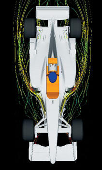
SOMETHING IN THE AIR
 A Formula 1 car is a feast of planes and curves, all working together to direct, resist or harness invisible forces. Here, Racing Line explains the aerodynamic principles that mould the car’s appearance
The importance of aerodynamics in Formula 1 is emphasised by the fact that the wind tunnel was the first part of the McLaren Technology Centre to be operational. In many ways, the tunnel is the heart of much that lies ahead, a temple to aerodynamic excellence, so Racing Line asked McLaren Racing’s Head of Aerodynamics Peter Prodromou to explain the intricacies of making a car aerodynamically efficient.
“Our role is to use the tools available to us – that is, the CFD [computational fluid dynamics] modelling simulation technique, the wind tunnel and the track – to gather data and make interpretations to generate an idea,” he says. “What we attempt to do is to exploit the fact that we can create downforce with the shape of the car and the devices we put on it. Where that helps is in providing the tyres with enhanced grip, predominantly in cornering – braking, turn-in and corner exit – when the driver relies on the grip of the tyres to carry speed.
“On top of seeking downforce, the major focus of the department’s work is in minimising disturbance, or drag, to the airflow around the car to enable us to get the most from the power we have available so that we can carry the highest top-end speed possible.”
As with all things in Formula 1, developments are being made all the time. “A few years ago,” Prodromou explains, “our aim was to increase downforce and decrease drag for improved efficiency. Now, we’re more interested in understanding the car when it has a yaw angle [the effect on the car in a crosswind and the slide experienced when cornering], when the driver steers the front wheels and when the car rolls due to lateral weight transfer, and we have the ability to do that now in our wind tunnel.
 “Cars used to be developed in the tunnel in a straight line and we’d look at the effect of the distance between the car and the road [ride height]. Now, as well as studying the car in yaw, steer and roll, we can also study it with differing exhaust blowing rates, reproducing different flow rates to correspond with different points around a circuit.”
There are sensors all over the car to help with this data acquisition. “Inside the wind tunnel model, we have equipment that tells us what forces the model experiences. In particular, we look at downforce, drag and side forces, along with all the moments of inertia. We also have sensors to measure pressure in and around the model and others that tell us what its ride height is as well.”
But a wind tunnel isn’t a real environment. It’s simulated and the tools used are always evolving. Until a few years ago, McLaren Racing used the National Physics Laboratory’s tunnel at Teddington in Middlesex, but having its own tunnel is a great step forward.
“The shortcomings of the previous tunnel were its remoteness from our base in Woking,” says Prodromou, “the fact that we couldn’t use it on a full-time basis and the fact that it hadn’t been built for our requirements. The one in the McLaren Technology Centre is tailor-made, offering faster wind speed and road speed [the tunnel has a rolling road] and temperature control.
“Ours is also more sophisticated in its ability to simulate real airflow around the car. We could fit a full-sized model in there if we wanted to, but 50 percent is a lot easier to use: it’s simpler to manufacture the components because you don’t need to worry so much about structural requirements.”
 Much of the fundamental research is done using CFD, though, and this is where Team McLaren Mercedes Technology Partner Sun Microsystems comes into its own, with its Technical Compute Farm linking all of the department’s Sun workstations through a high-performance network to enable the CFD team to analyse the aerodynamics of the whole car as well as individual components. They do this by using simulated airflow and ensuring that only the designs with the best performance are then produced.
“This certainly helps the aerodynamics team to be much more efficient,” says Prodromou. “For instance, to evaluate 10 front wings you used to have to design and manufacture all 10 and then undertake 10 tests. Now, we can evaluate these using CFD and then choose the one or two best to take further and send them to the tunnel and develop them there.
“Another real improvement is the ability to measure aerodynamic characteristics on a race circuit: we have the car instrumented in several ways.”
To collect data at a race track, Team McLaren Mercedes uses suspension pushrods carrying instruments that measure the forces the car experiences. However, verifying aerodynamic developments at circuits isn’t as easy as one might think, because the tracks have different characteristics: most need the car to have a near-maximum downforce set-up, with the exception of Monza (Italy) in particular, and Montreal (Canada), Indianapolis (the USA) and, it seems, Bahrain. At these tracks, a car goes faster with less downforce and reduced drag. Conversely, the team fits more wing, and thus drag, for Monaco and the Hungaroring (Hungary).
“When we look at circuits that we’ve never visited,” says Prodromou, “we rely on our engineers to key in the circuit dimensions and likely weather conditions to determine what will be the optimum set-up. That gives us a pretty good idea of what to expect and, once we’ve been there, past experience gives us a pretty good starting point for our next visit.
“We then bring the findings of all three techniques together, but our aim is to do it all in CFD, then verify our findings in the tunnel and on the track. “Modelling used to be crude and in some areas of the car it still is,” he says. “The rear wing is a good example of how modelling has advanced, because almost all of its development is done in CFD. We’re trying to improve confidence in modelling in other areas. The front wing is pretty good and we’re working at bringing the diffuser and indeed the rest of the car up to the same level.”
 One of the trickiest factors of an aerodynamicist’s job is that people can seldom analyse one part of the car at a time. “It’s difficult, because they all work in harmony. The main contributors to downforce are the front wing, the rear wing and the diffuser [the shaped underbody, especially at the car’s rear]. Their shapes work in harmony with the shapes of the chassis, nose, sidepods, upper body and other devices such as winglets and flick-ups.
“One of our major considerations is that we try to get the most from, say, the front wing without causing disruption to the other devices. It’s very easy to get the front wing giving downforce but to have this mess up the rest of the car. The art of what we try to do is to develop the front end to work in harmony with what lies behind it.”
The aerodynamicist’s labours aren’t always obvious to the untrained eye, though a subtle shaping here or there can make an appreciable difference. Barge boards, which direct airflow around the sides of the car, and turning vanes (smaller barge board-like components which sit just behind the front wheels) also have a part to play. “They manage the losses behind the front wing and the front wheels,” says Prodromou. “Wheels are not aerodynamic. They’re a huge source of loss and the aerodynamic structure behind the wheel interacts with the aerodynamic structures coming off the front wing. The barge board manages that as a damage limitation exercise.“
Spotting trends in barge boards is easy, but what is harder to appreciate is the diffuser. Little more than its tail can be seen poking out of the back of the car. “The key is its relationship with the rear wing in that one supports the other,” says Prodromou. “If you took our rear wing and tested it in isolation, it wouldn’t work. It’s too aggressive.
It would stall, like an aircraft trying to take off with its nose pointing too far upwards. The diffuser allows you to calm this design and vice versa. The whole thing is like a cascade. For example, the area at the end of a section of wind tunnel has a turn where there is a series of turning vanes. If you had just one turning vane, it wouldn’t work. What helps each of those vanes to work is the presence of the others: it’s a cascade. The relationship between rear wing and diffuser is similar, as is the relationship between the three bargeboards on the sides of our MP4-19.”
Aerodynamicists may not be fond of front wheels, but they’d also prefer it if there weren’t a cockpit opening and a helmet interrupting the airflow. “This area can affect rear-wing and airbox performance,” says Prodromou. “There are also more practical issues such as buffeting and driver comfort.
“The other area that people don’t appreciate is cooling for the brakes. There’s a compromise because you have to supply adequate cooling to the brakes, but whatever device you come up with to do this is going to be to the detriment of aero performance. So there’s a trade-off. It’s a similar story for cooling the engine. Everything comes at a cost, so we put considerable effort into finding solutions. At the same time, we work with our engine manufacturer to raise the engine operating temperatures so that fewer cooling devices are needed. However, Mercedes-Ilmor suffers similar constraints in that the more it goes in that direction, the less power it gets from the engine.
“That’s what it’s all about in terms of design: it’s one big compromise.”
THE FRONT WING
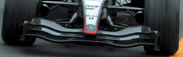 “The front wing is the most important part of a Formula 1 car’s aerodynamic package,” explains Team McLaren Mercedes Senior Aerodynamicist Doug McKiernan. “Because of its position, it controls how the air flows over the rest of the vehicle.
“Unlike the rear wing, the front wing utilises ground effect. This is the aerodynamic principle that uses the ground to accelerate the airflow to higher speeds than would be possible if the wing were in free air. The higher speeds generate lower pressures which suck the car down to the racetrack.” The wing’s optimum shape is determined using Computational Fluid Dynamics computer programmes, in conjunction with many hours spent evaluating a scale model in the wind tunnel.
The sport’s governing body, the FIA, has strict guidelines regarding the size of aerodynamic devices. The front wing must not exceed 1400mm across, by 550mm deep and 200mm high. However, there is no limit on the number of aerofoils within that specified area – unlike the rear wing, which is restricted to two. “In theory,” says Doug, “we could run 30, 40 or even more elements. However, typically we fit just three and this can drop to as few as two for a low-downforce circuit, such as Monza in Italy.”
The two rearward aerofoils are adjustable so that, between them, a driver and his engineer can fine-tune the handling of the front of the car. If the driver feels that his front tyres aren’t giving as much grip as he would like, for example, he can ask for an increase in the angle of the wing to give him more downforce and consequently more front-end grip. This can be carried out in a matter of seconds by inserting and turning an hexagonal wrench, or Allen key, in a screw thread located in the wing’s endplate. It is not unusual to see this done during mid-race pitstops to adapt the car to changing weather or track conditions.
The aerofoils are made of carbon fibre and are held together at each end by upright carbon fibre fins, known as endplates. The whole unit is suspended from the car’s nose by two pylons and held securely in place by four bolts. To test the rigidity of the structure, the endplate must be capable of withstanding the force of a 500 Newton weight applied to its upper edge.
Despite its sturdy construction, the front wing is prone to breakage, but not through aerodynamic stresses. Its position forward of the front wheels makes it vulnerable to accident damage. What might look like a gentle tap against another car in the first-corner mêlée at the start of a race is in fact a 150 kph-plus collision, which can seriously damage or remove the front wing completely. First-lap pitstops for a replacement nosecone and front wing assembly are therefore a frequent sight.
As you would expect, however, Team McLaren Mercedes does not subscribe to the philosophy of running on a wing and a prayer. It arrives at each grand prix fully prepared with six complete nosecone and wing sections, two for each race car and two for the spare, ready to bolt on at a moment’s notice.
THE REAR WING
 Formula 1’s constant quest for higher cornering speeds led 1960s designers to experiment with wing technology. An aircraft’s aerofoils are shaped so that air travelling over their top surfaces moves faster than that underneath, creating an area of low pressure. The higher pressure below then forces the plane skywards.
Now the last thing you want a racing car to do is take off, but if you invert the wing, the upward pressure becomes downward pressure, or downforce, clamping the car onto the track. So effective is current Formula 1 wing design that at speeds of more than 100mph they generate enough downforce for the car to stick to the ceiling.
The rear wing’s job is simple – to keep the back wheels of the car firmly on the track. It consists of a maximum of two carbon fibre aerofoils. These are stacked one above the other, like an outsize razor blade, and are individually adjustable through three different planes to cut the air at whatever angle is required.
Running along the full width of the trailing edge of each element is a small trim tab, known as a Gurney flap, which can be adjusted vertically to aid aerodynamic efficiency when the wing is run at a high angle.The aerofoils are held in place by upright vanes, or endplates. These are also made of carbon fibre, but sheathing a fire-retardant Nomex core.
The bottom edges of the endplates are mated to another winglike device, the lower main plane, which in turn is attached to the rear crash structure – a carbon fibre cone bolted onto the gearbox.
To comply with the technical regulations of motorsport’s governing body, the FIA, the whole wing assembly must fit within an area measuring 1000mm wide by 350mm long and 200mm deep. It has to be strong enough to withstand a load test of 1000 newtons.
The rear wing starts life as a mathematical equation, which needs to balance downforce against drag. It is resolved using Computational Fluid Dynamics and other number-crunching computer programs.
The final design finds physical form as part of a scale model of the car, destined for the wind tunnel, where it will give a clear indication of whether or not the engineers have got their sums right.
“Testing the rear wing in situ is crucial,” says Senior Aerodynamicist Doug McKiernan. “In isolation, it may perform well, but we need to see how it reacts in the more turbulent airflow generated by the car’s bodywork and wheels, and as part of the rest of the rear aerodynamics created by the lower main plane and underbody diffuser.
“We make high, medium and low-downforce rear wing packages to cater for the different circuits. Monaco, for example, is high downforce. The need for grip outweighs drag, so we put on every square centimetre of wing we can. By contrast Monza, in Italy, is the only true low-downforce track left on the calendar. There we remove one of the aerofoils altogether to reduce drag to a minimum on the long, fast straights.”
Whatever the wing package, there is no doubt that Team McLaren Mercedes’ cars will be flying come race day.
HEARTBEAT
 Formula 1 telemetry is the technological lifeblood of the sport, helping the drivers and engineers to better understand how a car functions and how they can optimise its set-up. But how does it all work?
“Information,” said former US President Ronald Reagan, “is the oxygen of the modern age.” Nowhere does that statement ring more true than in Formula 1, where a staggering flow of information has fanned the flames of a technological revolution.
Formula 1’s key figures exist in a bubble of publicity. Covered from every conceivable camera angle, their every move is broadcast to an audience of over 366 million people each race. Yet despite all of that interest the black art at the very centre of the grand prix drama, the use of telemetry data, remains shrouded in mystery.
Even one of the media’s most common phrases – ‘the drivers are studying the telemetry’ – betrays how little we know about the subject. Telemetry is the wireless transmission and reception of data for the purpose of remote monitoring. But, telemetry is merely the mechanism of the system. The numbers it carries, the data, are the precious figures that unlock the secrets of what is happening within the car’s central nervous system.
The roots of today’s complex telemetry systems can be traced back to the late 1960s. Engineers craved data with which to understand and develop the cars they were racing. Back then, the height of technical sophistication amounted to asking the driver to look down at the rev counter and other instruments on the dashboard at various stages of the lap. This information would be relayed to engineers when the car returned to the pits, whereupon they would attempt to reconstruct the lap.
Tyre manufacturers were among the pioneers of data collection. The movement gathered momentum in the early 1980s when the turbo era brought an even greater demand for quantitative data, and also better resources with which to pursue it.
These were heady times. Suddenly, top Formula 1 teams found themselves monitoring data with powerful mobile computers that, with hindsight, weren’t very mobile at all. Or that powerful.
“The capacity that these units had was probably less than that of a personal digital assistant now,” reveals Steve Hallam, Head of Race Engineering for Team McLaren Mercedes. “But these computers caused a ripple of excitement to run down the pit lane. Suddenly, engineers had vision – they weren’t just relying on what the drivers told them.” Where early data recording devices featured a handful of inputs from rudimentary sensors attached to the car, today’s complex telemetry systems allow the transmission of over 6000 parameters. These include detailed feedback on all aspects of the engine, transmission, suspension and wheels.
But why do we need telemetry data at all? After all, these drivers are the best in the world. If they can’t detect what’s going on within a car, who can? The problem, of course, is that while drivers may be good at conveying the ‘feel’ of a car, they can’t possibly know what’s going on in the heart of its sophisticated components.
The sensors’ ability to detect details more efficiently than the driver himself was demonstrated as recently as the 2003 British Grand Prix. Engineers watching the data screens noted that one of David Coulthard’s tyres was losing pressure in free practice. The team was able to recall him to the pits instantly, therefore averting the possibility of a sudden tyre deflation and accident.
Where ‘seat of the pants’ was once king, the set-up of cars is now largely dictated by data relayed from 120 sensors attached to the car. Initially, this technology was imported from other industries. Today, companies such as McLaren Electronics – which supplies Team McLaren Mercedes – are market leaders in their own right.
The information received by each sensor is harnessed simultaneously for many functions. For example, a simple wheel speed sensor determines far more than how fast the wheel is going. In conjunction with other sensors, it reveals how fast the car is going, its position on the circuit, and input to traction and launch control systems. Consequently, an enormous amount of information is generated: Team McLaren Mercedes engineers in the pits receive 50 Megabytes of data per car, per lap. That’s an astounding 3.5 Gigabytes per car, per race – enough to fill five CD-Roms. Phill Asbury, Head of Team McLaren Mercedes Systems Engineering, puts those figures in context. “If we were to type the information on sheets of A4,” he says, “the paper would stack to the height of the Empire State building!”
The sensors’ electrical pulses are processed on-board the car and beamed, via a digital radio signal, to an antenna mounted on the team’s truck. The signal is sent in the L-band microwave frequency range, around 1.6GHz. This range is used for ease of licensing, given the number of borders Formula 1 crosses, but also because it meets the team’s required bandwidth.
With five million single bits of information sent back from the car every second, Formula 1 is redefining the boundaries of data transmission. The high frequency required to handle that volume comes with some drawbacks.
Reception is very much line of sight. If the car goes through a tunnel, as in Monaco, or around the back of a hill, 100 percent coverage is lost. Monza, a tree-lined circuit in Italy, is the most challenging event for telemetry engineers. As you can imagine, few tears were shed when Hockenheim was reconfigured without its forest sections!
 “As systems have evolved, ‘sleight of hand’ techniques have been developed to cope with the temporary loss of signal,” explains Asbury. “The new McLaren Electronics system has a level of intelligence within it. When the car is in plain view we can re-transmit information that we know was not received previously when out of sight.”
Once received by the antenna, the signal is converted into ‘real’ figures. This data is distributed through a server on a 1Gb back-bone Ethernet system that utilises both fibreoptic and copper connections. It is sent simultaneously to each driver’s race engineer, to seven computer workstations, christened Battlestations, in the rear of the garage and to 11 terminals on the pitwall timing stands. In addition to a number of other track-based support personnel, data can also be relayed back to the factory in Woking via multiple ISDN lines.
The benefits of telemetry data are two-fold. Its careful analysis offers the chance to achieve the designer’s Holy Grail of improved reliability and performance. At a race, the Battlestation technicians are concerned primarily with diagnostics – checking that all the car’s systems are functioning correctly and providing early warning of a potential mechanical failure. It was this application that detected and rectified the onset of a fault in the engine oil system of David Coulthard’s car in Monaco last year. The Scot’s victory was hailed as a groundbreaking moment in the development of bi-directional telemetry. Sadly, this two-way feature has been a casualty of the 2003 rule changes.
Having accurate information enables engineers to fine-tune a car’s set-up. The graphic presentation of throttle, brake and steering traces also provides a tool with which drivers can maximise their own performance. During the course of a test or a grand prix, they will spend hours analysing such details.
The biggest leap forward in recent years has been the advent of real-time data. “Originally, all engineers had was downloaded data after the event had happened,” explains Hallam. “When data was downloaded after an engine failure, engineers would say, ‘The crankcase pressure went up. If only we could see that as it was happening, we could tell the driver to shut the engine down before it failed and we then wouldn’t be looking at a pile of bits and trying to work out what broke first’.”
Their prayers were answered by the advent of the data ‘burst’, triggered when the car passed the pit wall each lap. Even that wizardry has now been rendered obsolete by the latest McLaren Electronics technology, which offers continuous real-time coverage. The example of the wheel speed sensor puts that into context. The time delay between successive teeth on the car’s target wheel passing the sensor, and the sensor measurement appearing as a speed value in the pit garage, is an incredible 0.1 seconds.
With the stakes so high, Team McLaren Mercedes’ IT infrastructure receives the same meticulous attention to detail as that for the race cars. Computer Associates provides a range of software to protect the data from corruption. It is also responsible for a backup system that is on ‘hot standby’ in the event of failure. Technology Partner, Sun Microsystems, provides vital hardware for the Battlestations to help with the distribution and storage of data.
Team McLaren Mercedes uses two separate programmes to process data into an understandable format. The Advanced Telemetry Linked Acquisition System, or ATLAS, a McLaren Electronics programme, lends itself well to engineers making judgements about complex diagnostics issues. MIDAS, a programme written in-house, has been tailored primarily for the viewing of performance-related data.Recent restrictions on Formula 1 testing have served only to increase the importance of telemetry data. “Every minute waiting is a minute wasted,” suggests Asbury. In this respect, the introduction of McLaren Electronics’ new CBX600 couldn’t have been better timed. Boasting improved coverage and more data than rival systems, it has raised industry benchmarks.
“Twelve months ago, the cars would have to be physically connected to the system after a run and the high resolution data required for performance analysis uploaded,” explains McLaren Electronics Support Engineer Ed Gibson. “Often, a driver would be about to go out for his next run by the time the ‘overlay’ from the previous one could be put in front of him. This year all the data is transferred while the car is on the circuit. The printout is ready for a driver even as he rolls to a halt and pulls his visor up.”
Only when you witness the Team McLaren Mercedes telemetry system in operation at the racetrack do you realise exactly how advanced it is. When the car changes gear on the circuit, the action registers on the data traces quicker than the sound of the gearchange reaches your ears…
LOW-TECH, HIGH-TECH
 You would probably die of embarrassment if confronted with a picture of your first mobile phone. The same rosy-cheeked reaction is evident when Ed Gibson, support engineer for McLaren Electronics, views an image of the company’s first telemetry system.
In fact, there’s no need to wince. The system, complete with a formidable battery of monitors, was actually state of the art when it was devised for the Mercedes-Benz C291 World Sportscar programme in 1991. The comparison with the current system, introduced by Team McLaren Mercedes for this season, reveals how far the technology of telemetry has progressed in so little time.
Twelve years ago, the 20 screens displayed only engine diagnostics. Today, that technology could be accommodated on the screen of a single laptop computer. If all the parameters measured on this year’s Formula 1 cars were to be displayed on that 1991 system, it would require so many monitors that it’s unlikely there would be any room left in the garage for the cars.
THE WHEEL RIM
 A Formula 1 wheel is a piece of art, its flanks a blend of curves matched with a look of solidarity. Unlike many parts on a racing car, it’s relatively easy to understand the job done by a wheel, but the sort of wheel rims fitted to a Team McLaren Mercedes Formula 1 car are nothing like those on a typical road car.
Both are round, but there the similarities end. While weight on a road car wheel doesn’t make much of a difference, every single gram that can be saved on a Formula One car’s wheel is vital as strength and durability are balanced against lightness.
Each wheel is retained by a central wheel nut and receives its drive from the hub assembly via six drive pegs. There are 12 spokes, in six pairs, allowing hot air from the brakes to be ventilated through the wheel. Great gains have been made in this area over the days when cars ran with five solid spokes on the wheel rim.
The brake calliper sits within three or four millimetres of the inside of the rim, with the brake disc sited inside this. At the outside edge of the wheel rim, the surface has been shot-blasted to make it more abrasive at the point at which it meets the tyre bead so that they can grip better.
“The first thing that needs to be understood about a Formula 1 wheel is that there are dimensional requirement,” explains Head of Race Engineering Steve Hallam. “All wheels have to be 13 inches in diameter. A front wheel and tyre assembly has to lie between 305mm and 355mm. A rear wheel and tyre is 365 to 380mm. The diameter of a dry tyre can’t exceed 660mm, with a wet tyre allowed to be 10mm larger.”
There’s a further factor for the team to consider – the shape of Michelin’s new tyres for the season. Once this is known, the rim width can be finalised to bring the wheel and tyre within the rules. This is why a team’s wheels seldom arrive more than a few days before they need to be packed for transit to the opening grand prix.
Team McLaren Mercedes’ wheels are accurately machined from magnesium, a metal that’s chosen for its low density, by the Formula 1 team’s Official Supplier, Enkei.
Thoughts of using aluminium are dispelled, because, although it would be stronger, it would be too heavy. Carbon was once considered as a possible material, but this was banned, and all Formula 1 wheels must be metal under FIA regulations.
Monitoring the life of a wheel is vital, and this is why each of them is crack tested after 200km. It’s rare, though, that any wheel is used for more than 150km. Indeed, if a race is a two-stopper, they won’t do any more than 100km before being removed from the car.
Providing a wheel passes the crack test, its life could be as much as 3000km, but this depends, according to its weight and the material out of which it’s built.
Once again, radically different from the sort of life you would expect from a road car wheel rim, but this is just yet another reason why Formula 1 is such as fascinating and highly-specialised sport.
Technical Specification
Dimensions: Front 305-355mm; rear 365-380mm
Material: Magnesium
Number used per season: Up to 200 wheel rims are taken to each of the 16 grands prix in the Formula 1 season
BEHIND THE WHEEL

Without a steering wheel, even the world’s best Formula 1 drivers would find it hard to display their talents. The modern wheel does much more than just steer the car, however.
Ostensibly, the purpose of a steering wheel is simple enough – to transmit the driver’s input to the steered wheels of the vehicle in question – when that vehicle is a Formula 1 car, however, simple is hardly an appropriate term.
The steering wheels currently used by Team McLaren Mercedes’ drivers reflect the revolutionary changes that have occurred in Formula 1 steering wheel design – as well as technology in the sport as a whole – over the course of the past decade.
“The steering wheel of a modern Formula 1 car is one of the most intriguing parts because it is so visible,” admits Steve Hallam, Head of Race Engineering at Team McLaren Mercedes. “Most visitors to the factory or to the pit garage at a race get an opportunity to hold the wheel and pull the gearshift levers – the obvious bits. The majority of them then ask a perfectly logical question: ‘what do all the buttons actually do?’
“Well, if I answered that fully, I’d be giving away too many team secrets! I can say, though, that the steering wheel is a very complex piece of kit, which allows our drivers to perform a number of tasks aside from the wheel’s intended purpose – steering the car.”
Indeed, even as recently as 1992, the steering wheel on a Formula 1 car was a relatively plain, straightforward piece of equipment, round in shape, with a metal plate at the centre to attach it to the steering column, and generally no more than three buttons – one for selecting neutral, one for releasing liquid through a tube in the helmet for the driver to replenish his fluid levels and one for the radio.
The advent of complex electronic systems in Formula 1 throughout the 1990s changed all that, though, and a plethora of different functions began to be controlled by buttons and dials, placed on the steering wheel for ease of access by the drivers while racing. The onset of semi-automatic gear systems in the early 1990s heralded the arrival of ‘paddle-shift’ gear levers, mounted behind the steering wheel, which negate the need for the driver to remove his hands from the wheel to select a gear. This eliminates the possibility of a driver missing a gear, therefore increasing the smoothness and improving the timing of gearshifts.
Engine mapping, traction control and the advent of launch control programs that optimised the race start procedure all required various buttons and toggle switches to enable the driver to fine-tune his car’s settings while on-track. Modern Formula 1 steering wheels typically now include a clutch paddle, as this is only used when the car is leaving the garage, and eliminating the clutch pedal allows the car designers to further optimise the packaging of components in the footwell.
In 2003, then, the steering wheel is one of the most complex and high-tech parts of a Formula 1 car, with a typical wheel controlling at least 12 further functions in addition to actually steering the wheels. In spite of the confidentiality surrounding the functions controlled by the many buttons on the Team McLaren Mercedes steering wheel, here is a full guide to their secrets.
How Are They Made?
The manufacture of any part on a Formula 1 car is a complex process, and the steering wheel is no exception. Many different lightweight materials are used in its manufacture, including carbon fibre, aluminium, titanium, steel, rubber and plastic, and a complete steering wheel can take approximately 100 hours to produce from start to finish.
With the average steering wheel controlling as many as 12 separate parameters on the car, there is a large number of components, buttons and switches that have to be fitted during the manufacturing process – some 120 separate items in all. Yet, despite the myriad of materials and parts that make up each completed wheel, the weight of the finished unit, as fitted to the car, is just 1.3 kilograms.
During the season, a minimum of five steering wheels is constructed for each of the team’s two race drivers. Of these, three remain with the race team while two are held with the test team. In addition, third driver Alex Wurz has two wheels per season. However, during any specific Formula 1 season, more steering wheels will have to be manufactured, because it is a Team McLaren Mercedes policy that, when one of its drivers finishes a grand prix on the podium, the wheel from his car is removed and its history documented. It will then go into storage as a valuable souvenir of the team’s success, never to be used again.
PAINT SHOP BOYS
 The Team McLaren Mercedes colour scheme is one of the most stunning in the Formula 1 pitlane, but it requires a team as specialised as the mechanics who assemble the car to ensure it remains the best on the grid. Meet the Team McLaren Mercedes paintshop crew…
If looks won races, then Team McLaren Mercedes would be Formula 1 world champions every season. Thanks to the team’s unique and readily-identifiable colour scheme, its cars are guaranteed to cut a shine at the front of the grid, and always look the best in the pack.
That quality of presentation shouldn’t be underestimated in an arena where, more than any other sport, image is king. Maintaining such high standards is the role of McLaren’s paintshop, under the leadership of manager George Langhorn. It is impossible to appreciate the subtleties of the team’s colour scheme when you watch a grand prix. See the livery at close quarters, though, and it is immediately apparent why it takes three days to paint just one chassis. Your local garage could probably spray your road car 30 times over in that time, but, somehow, you just know the final result wouldn’t be the same.
”The paints we use are automotive-based and relatively similar to those you would see if you had your car painted at a typical garage,” George explains. “But the level of preparation, like the application of the colours, is completely different.”
The process begins with the car parts in bare carbon fibre form. Weight is so critical on a Formula 1 car that, even if a chassis is being repainted, the existing layers must be totally stripped. The preparation is so meticulous that this process alone can take an entire day. Where paint adheres easily to steel or aluminium, the work is far more complicated when carbon fibre is involved. Air bubbles trapped between the layers are an ever-present threat, as they can cause solvent entrapment. To overcome this, parts are ‘de-greased’ - a procedure that entails painstaking sanding down of the carbon fibre. Where necessary, tiny amounts of filler are used to eliminate imperfections.
An undercoat of primer is the next step, again applied with the utmost care to avoid excess weight. This coat helps clear any remaining pinholes, and is force-dried at 60 degrees centigrade for 30 minutes.
The team’s current spray booths are combination units that double as ovens. This level of sophistication amuses George Langhorn when he reflects on how far the process has come since he worked on the race team in the 1970s.
”Nowadays, you take spare parts that are painted, ready to go, but it was a different era then - one in which teams didn’t have that capability,” he recalls. “The spares they took weren’t even painted. If repairs were needed, they were done on-site. Conditions were often terrible. In Brazil, in 1979, one of the newspapers printed a shot of me spraying the top body of a car in a shed. It was absolutely boiling!”
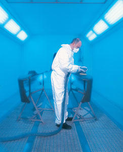 Just how far the sport has developed is evident in the spotless nature of today’s spray booths. They really are as sterile as operating theatres, and the work within is equally precise. The colour coats are carefully applied only after the layer of primer has once again been thoroughly de-greased.
Every component is weighed both before and after it is painted, and the results are collated by the drawing office. Occasionally, stories circulate that new teams’ paint schemes are ‘too slow’. Such tales appear to be rooted more in mirth than in reality. Surely the spraying of a car can’t really affect its driver’s chances of spraying the champagne? You’d be surprised, though.
”We can’t be seen to be putting on pounds when every other department is saving ounces,” George points out. “There are certain areas of the car we don’t paint, such as the underside of front wings and certain areas of the rear wing. We can keep the weight down by just painting the bit that people can see, and then polishing the carbon fibre underneath for effect.
”Also, we can’t have very sharp, hard lines anywhere because they upset the boundaries for the first layer of air that goes over the rear wing. The same goes for decals. They are cut on a machine in this department. The whole of the rear wing is screen painted so that there are no edges.”
The introduction of a new Title Partner for the McLaren-Mercedes team in 1997 was a seminal moment for the paintshop. It required not only a startling new colour scheme, but also a whole new approach. When the department first saw the design, a collective intake of breath could be heard. To McLaren Group Chairman and CEO Ron Dennis, the subtle mix of metallic colours conveyed ‘dignity and class’. For those faced with reproducing the scheme, the word ‘nightmare’ sprung to mind.
”When we first saw it, my reaction was ‘how are we ever going to do that?’,” confesses paintshop supervisor Alan Moffatt. ÒIt has changed the way we operate. Before, any of us could do the job all the way through. Now, we rely heavily on a good airbrush artist, Lawrence Manning, and we work much more as a team.”
The base colours - black, silver, white, graphite grey and bright red for the nose and ‘ticks’ - are applied to the bodywork in blocks pre-designated by Manning. He then uses the airbrush - a pen-like tool that would give anyone aspirations to be Michelangelo - to blend the colours and soften the lines. His skill gives the final flourish to his colleagues’ work. If the paintshop were a football team, Manning would be the star striker who steals the headlines, but he stresses that he is merely the man on the end of what is very much a team effort. “I’ve worked for outside companies, and the guys here are by far the most talented I’ve seen,” he says.
An illustrator by trade, Manning once earned a living by customising T-shirts and surfboards on a beach in Greece. He gets considerably less sun in Woking, but far more satisfaction. “We never actually see the whole car bolted together in the paint shop,” he says. “It’s a buzz to see it on television and think that 366 million people are looking at something we did.”
 The new livery presented many challenges, not the least of which was how to accurately replicate such a complex blend of colours. All of the car’s components are interchangeable, and the team will take six nosecones, for instance, to every grand prix and test. The colour scheme must join seamlessly when each of those six is mated to any of the eight chassis that are rotated through the department. To ensure pinpoint accuracy, a fibreglass mock-up of the chassis resides in one corner of the paint shop. It is approved by Ron Dennis and the Graphics Department at the start of each year, and serves as a template for all subsequent work from then on.
The scientific approach extends beyond the car itself, to the equipment that McLaren’s six paint sprayers have at their disposal. When George Langhorn first started in Formula 1, 25 years ago, a handkerchief tied over your mouth constituted the ultimate in safety gear. Today, workers use high-velocity, low-pressure spray guns in which the paint enters the gun at 65psi, but atomises at 12psi to reduce fumes. They also wear full breathing apparatus that, not so long ago, would have been seen only on the set of a science fiction film.
There’s nothing fictional about McLaren’s legendary high standards, though. “You know what the standards are, because Ron sets them himself,” George points out. “His attention to detail is phenomenal, and that sort of commitment is ingrained in everyone.” Just as the team has been a pioneer in so many areas, so its use of airbrushing has taken car livery to new levels. Two layers of full gloss lacquer are added after Manning has worked his magic. The car is baked dry once more, again at 60 degrees centigrade for 30 minutes, then given a final polish before the Partners’ decals are applied to the finished product.
The paintshop is involved at both ends of the production run. When a chassis is returned to base with damage, the paintshop strips it to enable a full inspection of the carbon fibre. When the car is ready again, the paintshop is its last stop before departure for the track. The truck to European grands prix must leave on Monday lunchtime, and the pressure is on. It’s a case of ‘coming, ready or not’, because airline officials get a bit stressed if you try carrying a chassis in hand luggage!
As well as painting the team’s race cars, the paintshop is also involved with producing each and every item used by the team that carries the Team McLaren Mercedes livery. Its workload ranges from spraying pit equipment and the mechanics’ fireproof helmets, to helping plan the paint scheme on the team’s trucks. Tasks such as McLaren Cars’ entry for the Goodwood Soapbox Challenge rank among its less publicised projects.
But ultimately, in the paintshop, as at the circuit, everyone is racing against the clock. That battle can be won only with excellent organisation and planning. Who said that looks were everything?
Comments:
Post a Comment
![]()